Spaceborne Electronic Enclosure Mechanical Design
Client – Aerospace company
Capabilities Demonstrated
Rugged design for stringent environmental requirements
- Human factors / user interface design
- SWaP (Size, Weight and Power) analysis and design
Integration of electrical and mechanical parts and subassemblies
Design for Manufacturability (DFM)
- Design for Assembly (DFA)
Manufacturing supply chain vendor selection support
- 3D mechanical design and simulation with SOLIDWORKS
Challenge
AppliedLogix was tasked with developing an electronics enclosure that would withstand the thermal and mechanical stresses, including the vibrational loading during launch, that results from being placed in a zero-G earth orbit aboard a space launch vehicle. The enclosure design needed to support multiple interconnected printed circuit board (PCB) assemblies, while meeting stringent electromagnetic compatibility (EMC) standards, and providing robust connector mounting for customer harnessing between modules and test apparatus.
Solution
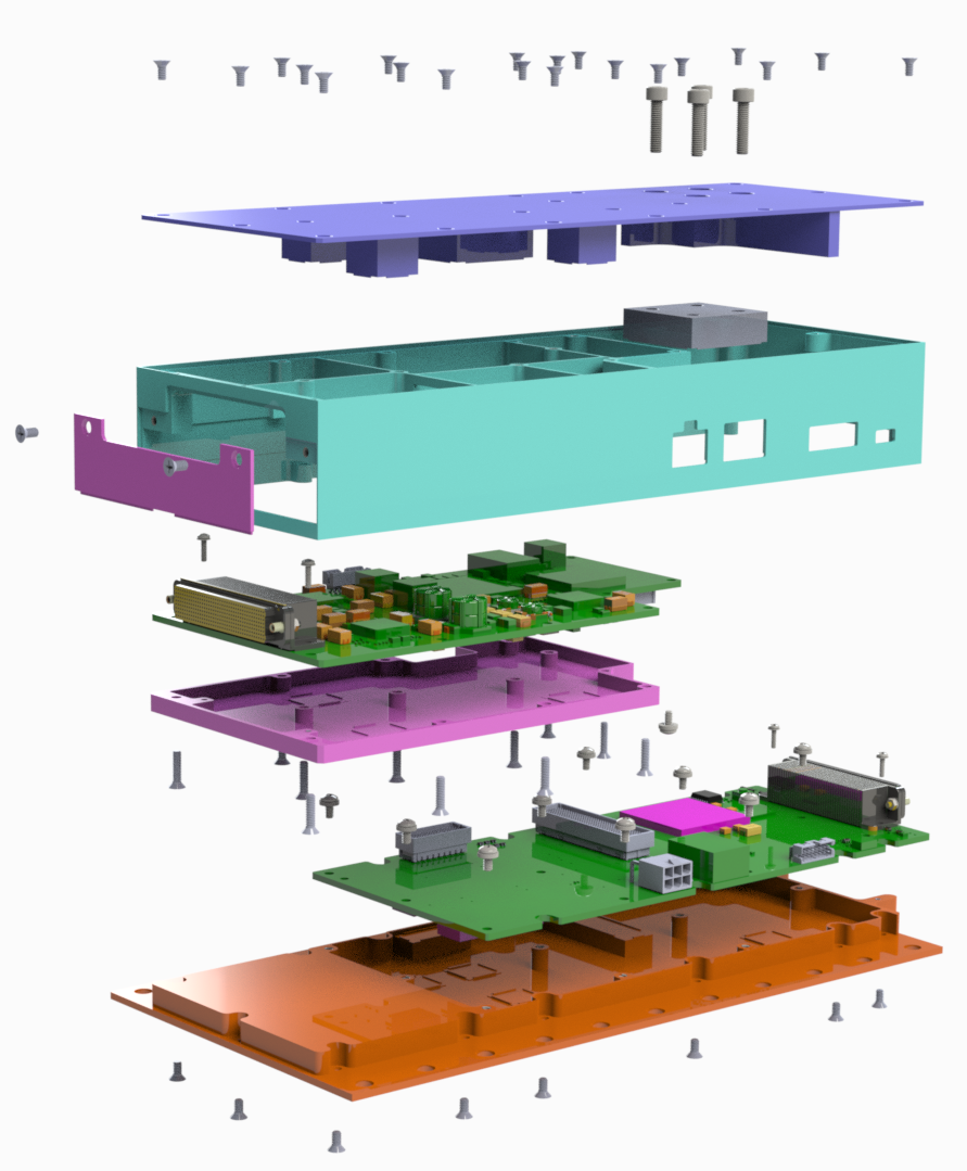
A machined aluminum enclosure was developed. The unique design supported the top down assembly of the boards onto their respective enclosure compartments. The top cover, mezzanine board bottom cover, and the baseplate all required heatsinking features that were used in conjunction with thermal gap pads to conduct heat off the boards.
Once the two sub-assemblies were pre-assembled, the housing and baseplate were constructed in a manner to provide the structural support needed to oppose the mating forces of the high-density connectors during assembly.
The assembly cover with thermal gap pads along with the end cover were installed last. These enclosure elements were designed to physically protect, electrically isolate, and thermally dissipate heat from the FPGA components installed on both the mezzanine and motherboards.
SolidWorks was deployed to both define and verify the proper alignment of board connections, mounting points, and interfaces. Enclosure details were modeled and evaluated for proper clearances and hole alignments between components. Connector locations and user access points were modeled and evaluated with the customer and were then fed forward to our PCB layout tools.
![]()
Once the PCB layouts were completed and fully populated board models were available, then the mechanical components were detailed and sourced for manufacturing. Upon return from manufacturing, critical to function dimensions were captured and reported. Complete board and enclosure assemblies were provided to the customer for flight simulation evaluations.
Benefits
- Customer received complex electro-mechanical integration services for a spaceborne subsystem from a single source
- High functionality design
- Robust board mounting features and environmental protection
- Easily manufactured and assembled